


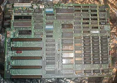
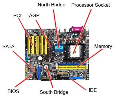

Your computer isn’t just a box of random parts. It’s a system where every component talks to the others. The motherboard is the central hub that makes that conversation possible. Without it, your CPU, memory, and expansion cards wouldn’t connect.
Зміст
What Actually Sits on a Motherboard?
A standard motherboard is crowded. It has dedicated slots and sockets for critical hardware. You’ll find:
- CPU (Central Processing Unit) socket
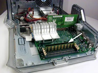
- RAM (Random Access Memory) slots
- AGP and PCI expansion slots
- Power connectors and BIOS chips
Think of the motherboard as the nervous system. It routes data and power between the brain (CPU) and the working memory (RAM), while also letting you plug in extra hardware like graphics cards or sound boards.
Why These Slots Matter
Each slot serves a specific job. The CPU socket holds your processor. RAM slots allow you to add more memory, which speeds up multitasking. AGP and PCI slots let you add specialized cards. AGP was designed for graphics, while PCI handles a wider range of peripherals.
The layout matters. A close-up of these slots shows how tightly packed the board is. Every component needs a clear path to communicate. If one slot is blocked or misaligned, the whole system slows down or fails.
Understanding your motherboard helps when you upgrade. Want more RAM? Check the slots. Need a better GPU? Look for AGP or PCI availability. The board dictates what’s possible.
The motherboard isn’t just a circuit board. It’s the architecture of your entire PC experience.
What’s next? We’ll break down each slot and part in detail, showing you exactly what to look for when you open up your machine.
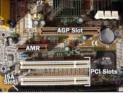

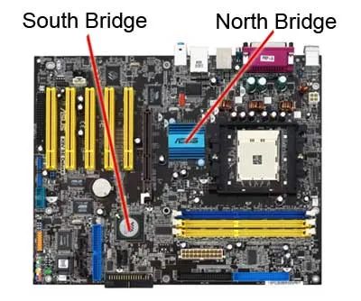
How the chipset handles data flow
The chipset acts as the connection hub. It links the CPU to everything else on the board. Without it, your processor would be floating in space.
Think of it as glue. It holds the microprocessor to the memory, slots, and peripherals. On standard PCs, this glue splits into two distinct chips.
The north bridge and south bridge
These two components handle different speeds and tasks.
- North Bridge : Connects high-speed components directly to the CPU. This includes system memory (RAM), the AGP slot for graphics cards, and often the PCI bus.
- South Bridge : Manages slower I/O functions. It handles USB ports, audio, legacy ISA slots, and IDE controllers for hard drives.
Why the split? Speed. The north bridge sits close to the processor to minimize latency for data-heavy tasks. The south bridge handles background chores, keeping the CPU free for performance-critical work.
Have you ever wondered why early graphics cards plugged directly into the motherboard instead of a general-purpose slot? That’s the AGP connection. It was a direct line to the north bridge, bypassing the slower PCI bus entirely.
Where memory fits in
RAM connects to the north bridge. Not the south. Not the CPU directly (in most architectures of this era). The north bridge manages the flow of data between the processor and your volatile memory.
This matters for upgrade paths. When you buy new RAM, compatibility depends on the chipset’s memory controller, not just the physical slot. Some chipsets supported SDRAM, others DDR, and later, DDR2 or DDR3. Mixing types usually meant the board wouldn’t boot.
The south bridge, meanwhile, deals with your storage. If you’re installing a new hard drive, the IDE or SATA controller lives on the south bridge. USB hubs? South bridge. Sound card? South bridge.
So when you open a case and see that small chip tucked under the heatsink near the CPU, that’s likely the north bridge. The larger chip near the expansion slots? Probably the south bridge.
And yes, they’re separate. For now. Future chipsets began merging these functions, but for the era this describes, two chips were standard.
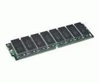

Why SIMMs and DIMMs Still Matter for Your System Speed
RAM isn’t just a storage bin. It’s the scratchpad for everything your CPU is doing right now. If that scratchpad is too small or too slow, your whole machine feels sluggish, no matter how fast your processor is. The physical package matters. Specifically, how those sticks connect to your motherboard dictates bandwidth and upgrade paths.
Single in-line memory modules, or SIMMs, were the standard for a long time. They had a single row of pins on one side of the board. Simple design. But limited data width. Most SIMMs were 32-bit. That meant your system needed multiple modules to get the full memory bandwidth your CPU wanted.
Then came DIMMs. Dual in-line memory modules. Pins on both sides. That doubled the data width per module. A single 32-bit SIMM became the equivalent of two 32-bit DIMM channels in terms of physical space and connectivity, but with better electrical isolation and higher density potential.
Why does this matter to you today?
- Upgrades: If you’re buying used hardware, you need to know which socket type your board has. Mixing SIMM and DIMM slots is physically impossible and electrically dangerous if forced.
- Bandwidth: DIMMs allow wider data buses per stick. This means higher throughput without needing eight tiny SIMMs soldered to the board.
- Heat and Stability: DIMMs have better pin spacing, which reduces electrical crosstalk. Less noise. More stable signal integrity, especially at higher clock speeds.
The shift from SIMM to DIMM wasn’t just about more pins. It was about decoupling memory width from module count, letting systems scale performance without cluttering the motherboard.
How to Tell If Your Machine Uses SIMM or DIMM
Look at the physical edge connector. One row of gold contacts? SIMM. Two rows, one on each side? DIMM.
Older laptops and desktops from the mid-90s to early 2000s often used SIMMs. Most systems from the late 1990s onward moved to DIMM. DDR, DDR2, DDR3, DDR4, and DDR5 are all DIMM variants, just with different pin counts and electrical specs.
Key difference: SIMM = single row of pins. DIMM = dual row. That’s the core physical distinction. Everything else flows from that geometry.
If you’re troubleshooting performance issues, check your manual or search your motherboard model. Knowing the RAM type helps you buy the right upgrade. A DDR4 DIMM won’t fit a SIMM slot. No adapter fixes that. It’s a fundamental architectural choice baked into the board layout.
Memory speed is only one variable. The interface between the module and the chipset determines how fast data actually moves. A fast CPU with slow or narrow memory bandwidth hits a wall. That’s why matching your RAM type to your platform isn’t optional. It’s foundational.
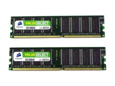

SIMM vs. DIMM: The Bandwidth Difference
The hardware gap between old and new memory modules comes down to data width. A SIMM (Single In-line Memory Module) carries a 32-bit path to the memory chips. A DIMM (Dual In-line Memory Module) doubles that, offering a 64-bit path.
This isn’t just a spec sheet detail. It changes how much data moves at once. If you are still hunting for upgrade paths for legacy systems, this distinction matters.
Where Small Memory Modules Live
Not every machine uses standard desktop DIMMs. A smaller type of memory module is common in space-constrained devices. You will find them in:
- Notebooks
- Printers
- Networking equipment
These compact modules handle the specific footprint requirements of portable and embedded hardware.
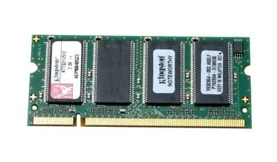

SODIMM stands for small outline dual in-line memory module. It is roughly half the size of standard DIMM sticks. These compact modules handle integrated circuits efficiently. They fit into laptops and small form factor desktops where space is tight.
How SODIMM differs from standard DIMM
You will not find SODIMM in most tower PCs. Those systems usually take larger DIMM cards. SODIMM saves physical space. That trade-off means fewer pins and a smaller footprint. The electrical architecture remains similar, though. Both types transfer data between the CPU and storage. The difference is purely physical.
Space constraints drive memory module design.
Why does this matter? If you are upgrading a laptop, you need SODIMM. Buying a standard DIMM will not work. The slot shape is different. The pin count does not match. You might think any RAM is interchangeable. It is not. The physical form factor dictates compatibility.
Check your manual before buying. Look for “SODIMM” specifically. Some mini PCs and all-in-ones also use these smaller sticks. Knowing the difference prevents wasted money. You avoid buying parts that simply do not fit.
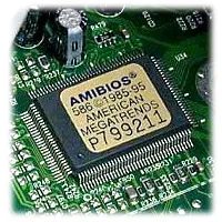

What is BIOS and why does it run first?
You see it before the OS loads. It’s called the Basic Input-Output System, or BIOS.
Think of it as the computer’s bootstrapper. When you flip the switch, electricity flows, and the CPU starts looking for instructions. It can’t load Windows or Linux yet. The hardware is raw. The BIOS lives in a small chip on your motherboard, and it wakes up first.
It checks the RAM. It talks to the CPU. It initializes the drives. Without it, the machine sits in a state of silent confusion.
How does BIOS relate to your RAM upgrade?
Here is the connection you might be missing.
If you add more RAM, the BIOS has to recognize it. Newer motherboards use UEFI (Unified Extensible Firmware Interface), which is the modern successor to legacy BIOS. Older systems still run pure BIOS.
Why does this matter for you?
- Compatibility: Some old BIOS versions won’t see 16GB or 32GB stick configurations if they weren’t designed for high-density memory.
- Speed settings: The BIOS/UEFI interface is where you tell the motherboard to run that RAM at 3200MHz or 3600MHz. Leave it on default, and you might be throttling performance.
- Boot order: If you install a new OS on a different drive, the BIOS controls which drive the computer tries to read first.
Which version should you be running?
Most computers from 2010 onward use UEFI. It’s faster, more secure, and handles larger drives. Pure BIOS is legacy.
If you’re upgrading an older machine, check your firmware. It’s usually available on the motherboard manufacturer’s website. Updating the BIOS can fix bugs that prevent new RAM from being detected. It’s not glamorous work, but it’s often the difference between a smooth upgrade and a headache.
The next step is understanding how the OS takes over from that initial handshake.
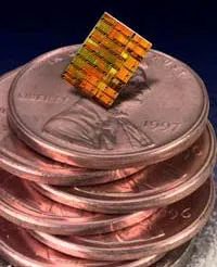

What is a microprocessor and how does it work?
A microprocessor is a complete computation engine. It’s also called a CPU or central processing unit. The whole thing, every circuit and control logic, sits on a single chip. No separate boards. No scattered components. Just one dense package doing the thinking.
How did supercomputers start using microprocessors?
High-performance versions of these chips weren’t always desktop-only. Some microprocessors were built specifically for supercomputers. Think of those as the early powerhouses, where raw speed mattered more than energy efficiency or compact design. A microprocessor in a supercomputer context isn’t just a scaled-up office chip; it’s engineered for parallel throughput, massive data pipelines, and sustained computational load.
Which processors were originally used in supercomputers?
The specific high-performance processor mentioned in the source was originally deployed in supercomputers before trickling down to other uses. The exact model isn’t named in the text provided, but the point is clear: microprocessors didn’t start as consumer gadgets. They started as specialized silicon for institutions that needed serious compute power. The transition from supercomputer-grade to general-purpose hardware is a big part of why modern chips are so capable.
Why does the single-chip design matter for everyday users?
Because everything is on one chip, you get integration. Less wiring, less heat between components, lower latency for internal operations. That’s why your laptop, phone, or even smart fridge can do tasks that would have required a room of equipment in the 1970s. The microprocessor made computing portable. It made it cheap. It made it accessible.
How is a microprocessor different from just a “processor”?
The terms are often used interchangeably, but microprocessor emphasizes the single-chip architecture. A “processor” in a broader sense could refer to any unit that processes data, including multi-chip systems or discrete logic boards. The microprocessor is specific: one chip, doing the full computation engine job. That’s the distinction that matters when you’re reading specs or comparing hardware.
A microprocessor is not just a part of a computer. It is the computer’s brain, all on one piece of silicon.
Where do you see microprocessors in daily life?
Everywhere. Your phone. Your car’s engine control unit. Your microwave’s timer. Your gaming console. The common thread: a single chip handling logic, arithmetic, and control flow. The supercomputer roots explain why modern microprocessors can handle tasks like video decoding, AI inference, and real-time rendering without breaking a sweat.
Why should non-experts care about this?
Because when you’re buying a device, the microprocessor is the first spec to check. Not the screen. Not the storage. The chip. It determines how fast things open, how smooth gaming feels, how long the battery lasts under load. Understanding that it’s a single-chip computation engine, with a history stretching back to supercomputers, changes how you read a spec sheet. You’re not just looking at a number. You’re looking at the architecture of a machine that’s been shrinking and speeding up for decades.
The chip doesn’t get a lot of credit in casual conversation. But it’s the reason your laptop fits in a backpack and your smartwatch can track your heart rate while

The Bridge Between Processing Power and Storage
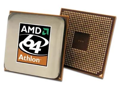
8GB of RAM and a 64-bit CPU? Nice. Your Athlon 64 X2 4800+ is humming along. It chews through data, spins up threads, and handles multitasking without breaking a sweat. But here is the problem: a processor does not hold data. Not even for a second.
When you close that window, when you shut down the system, that information is gone unless it has a home. That home is your hard drive.
The transition to 64-bit architecture changed how the CPU talks to memory, but it didn’t change the fundamental role of the disk. It is still the long-term memory. The CPU processes; the drive stores. You need the hard drive on the next page to store all the information processed by your computer. Without it, that powerful 64-bit engine is just a very expensive calculator that forgets everything the moment you stop using it.
Think of the CPU as a chef’s hands. Fast, skilled, capable of complex moves. The hard drive is the pantry. If the pantry is empty, the hands are useless. In this 8GB/64-bit setup, the bottleneck isn’t usually the processor anymore. It’s often how fast you can pull that data from the disk into the RAM for the CPU to touch.
So, while the Athlon 64 handles the logic, the hard drive handles the persistence. Everything you save, every program you install, every file you create lands there. It is the silent workhorse behind the scene.

Anatomy of a Sealed Aluminum Box
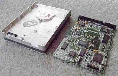
The hard disk drives you probably have sitting in your desktop or laptop aren’t just spinning coins in a vacuum. They are precision-engineered sealed aluminum boxes. When you pop the top off (don’t try this at home, the dust particles are microscopic and will destroy the data), you see the guts.
The controller electronics live on one side. That little board does two heavy jobs. It manages the read/write mechanism, the tiny arm that darts back and forth across the disk surface to grab bits and bytes. It also drives the motor. That motor spins the platters at high speed, the same ones you see in the close-up shots of the internal components.
How the Controller Drives the Mechanics
Why is the controller so important? It’s the brain. Without it, the platters just spin uselessly. The controller sends precise electrical signals to the voice coil motor, which moves the actuator arm. It also regulates the spindle motor speed.
You might wonder where the data actually sits. It’s etched into the magnetic coating on the platters. The read/write head floats nanometers above the surface. It never touches. If it did, you’d have a head crash and total data loss. The sealed box exists to keep the air clean enough for that tiny gap to remain stable.
- Controller board : Manages electrical signals and data translation
- Spindle motor : Spins the platters at specific RPMs
- Actuator arm : Positions the read/write head
- Platters : Store the magnetic data
The whole assembly is a dance of physics and electronics. Miss one timing window, and your file is gone.
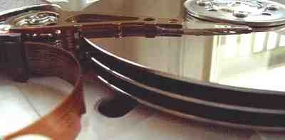

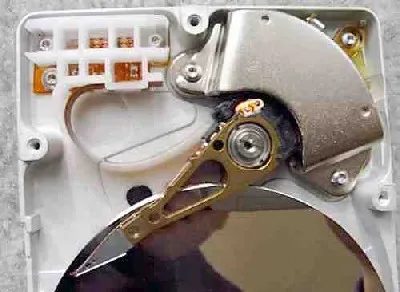
The mechanics under the hood: platters, heads, and the arm
Three platters. Six read/write heads. That is the physical reality inside this specific drive. Those platters, often called hard disks, spin while the heads hover just above the surface, capturing or laying down data in fractions of a second.
The arm is the piece of hardware most people overlook. It holds those heads and has to move with terrifying precision. One arm per head. All six aligned to function as a single unit. If the arm misses its target by a fraction of a micron, the data is garbage.
Speed matters here. The arm has to position itself over the correct track almost instantly. That is why the design prioritizes rapid, accurate movement over bulk. The connection between this mechanical assembly and your actual PC is where the translation happens, turning spinning magnetic patterns into files you can open, edit, and delete.
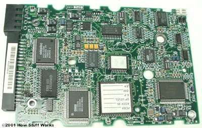

How IDE drives connect to your PC
If you opened an old tower in 2005, you saw that cable. The Integrated Drive Electronics interface was the default choice for hard drives and optical drives. It wasn’t fancy. It worked. You plugged it into the motherboard, attached the power, and the OS found the storage. No drivers needed for basic operation in most cases.
What IDE actually does under the hood
IDE isn’t just a wire. It’s a protocol. It defines how the controller talks to the disk platters and how the motherboard negotiates data transfer. The interface handles timing, error checking, and command execution. When you clicked “Save,” IDE managed the handshake between your application and the physical write head. It kept the conversation simple enough that hardware manufacturers could ship drives without complex firmware negotiations.
Why it dominated for a decade
Cost. That’s the answer. IDE cables were cheap. Motherboard chips were integrated, so you didn’t need an expensive controller card. Compared to SCSI, which required specialized hardware and driver stacks, IDE was plug-and-play for the average user. Home builders and OEMs preferred it because it reduced assembly time and lower Bill of Materials. A typical IDE channel could support two devices: one master and one slave. That was enough for a system drive and a backup drive or CD-ROM.
IDE vs. the alternatives of its time
SCSI offered better performance and more device attachment, but it demanded expertise. SATA arrived later, offering thinner cables, hot-swapping, and higher bandwidth. IDE never caught up to those speeds. But for the era it ruled, it was the practical choice. You didn’t need RAID. You didn’t need 150MB/s transfers. You needed a 40GB drive that held your music and documents. IDE delivered that reliably.
How the physical connection works
The 40-pin ribbon cable is distinctive. It runs from the motherboard to the drive. Pin 1 aligns with the drive’s connector, usually marked by a colored stripe. Power comes from a separate 4-pin Molex connector. The motherboard’s IDE controller chip handles the low-level communication. If you installed two drives on the same channel, you had to set jumper positions on the drives to designate master and slave. Get that wrong, and the system wouldn’t boot.
Where IDE still shows up today
Not in new PCs. Not even in most used systems from the last five years. But legacy servers, embedded devices, and repair labs still deal with it. If you’re refurbishing a 2003 workstation or maintaining an industrial controller, you’ll encounter IDE. The interface hasn’t disappeared from the physical world, just from the consumer market.
Which systems used IDE exclusively
Most desktops from the late 1990s through the mid-2000s relied solely on IDE. Laptops followed later, adopting PATA variants of the same protocol. The transition to SATA happened gradually, first in high-end desktops, then in consumer laptops. By 2008, new builds almost universally shipped with SATA ports. IDE became the legacy option.
The real advantage of IDE was simplicity. You didn’t need to understand bus mastering or command queuing. You just connected it.
What happened to the interface
It didn’t vanish. It became redundant. SATA
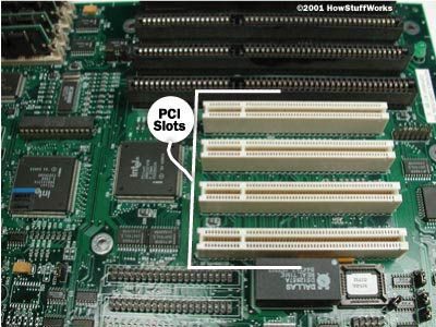
How the PCI Bus Enables Direct System Memory Access
The Peripheral Component Interconnect, or PCI, bus connects hardware directly to your system memory. That direct link matters. It cuts out the middleman that slower buses rely on. You plug a network card, a graphics card, or a sound card into a PCI slot, and the data moves efficiently between the device and the rest of your computer. The architecture is designed for speed and direct interaction.
Direct access to system memory is what makes PCI slots effective for high-bandwidth peripherals.
Why does this specific routing help? Because it reduces latency. When a graphics card processes a frame, it doesn’t wait in a queue behind unrelated data. It talks straight to the RAM. This is why you’ll find these slots reserved for components that need consistent, fast data throughput.
Which components typically occupy these slots?
– Network adapters
– Graphics cards
– Sound cards
These are the workhorses. They rely on the PCI bus to move large chunks of data without choking the system bus. The design is straightforward. One connection. One path. Fast data transfer.
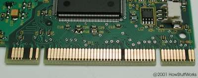

From 47 Pins to Slot Wars: The End of PCI for GPUs
That’s 47 pins doing the heavy lifting. Each one is a thin metal foot, a tiny bridge between the chip and the circuit board, carrying data and power to the PCI slot. It worked. It was standard. It was how you plugged a graphics card into your PC for a decade.
But it wasn’t fast enough, not anymore.
The next piece of hardware didn’t just improve on PCI; it replaced it as the standard way to connect a graphic card. The gap between what PCI could deliver and what new 3D gaming and professional visualization software demanded became too wide to ignore. Bus width, bandwidth, and latency all pointed the same direction: PCI was a dead end for GPU connectivity.
Why PCI Stalled: The Bandwidth Ceiling
PCI ran at 33 MHz with a 32-bit bus, topping out around 133 MB/s. For 2D graphics, it was fine. For pushing thousands of polygons per frame with texture mapping? It choked.
Developers and hardware makers needed more lanes. More parallelism. More direct communication between the CPU and the GPU. PCI’s shared-bus architecture meant every device on the bus competed for the same pipe. Add a network card, a sound card, and a hard drive controller, and the GPU got starved.
The Aggressive Alternative: AGP Arrives
Accelerated Graphics Port, or AGP, was designed from day one to do one job: get video data from the system memory to the GPU without clogging the main CPU bus.
It used a dedicated point-to-point connection. No more sharing. No more contention. AGP 1.0 ran at 66 MHz with a 32-bit interface, doubling PCI’s bandwidth to 266 MB/s. Later versions pushed that to 1.3 GB/s at 333 MHz. The pin count dropped, the protocol got smarter, and the GPU got a private highway.
What Changed for the User
You didn’t see the pins. You saw the frames per second. You saw textures that didn’t shimmer. You saw 3D games that didn’t stutter during fast camera pans. AGP let the GPU access system RAM directly for texture storage, a feature called fast write combining that PCI simply couldn’t support.
It also meant physical compatibility. A PCI card wouldn’t fit an AGP slot. The connectors looked different. The locking mechanisms were different. You couldn’t just plug your old GeForce 256 into a new AGP motherboard. It was a hard break, and the industry made sure you knew it.
The Last Stand: Why PCI Lived On
PCI didn’t die overnight. It hung on for peripherals. Network cards, sound cards, and USB controllers still used PCI long after AGP took over graphics. The standard was too entrenched, too cheap, and good enough for non-GPU devices.
But for graphics? The slot war was over. AGP owned it until the next generation arrived, one that would make both PCI and AGP look like relics from a slower era.
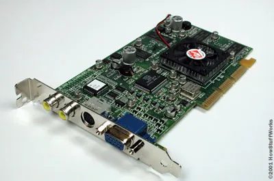

How AGP Accesses System Memory on the Fly
An Accelerated Graphics Port (AGP) changes how your computer handles video data. Instead of relying solely on the memory soldered directly to the graphics card, the operating system can dynamically assign system RAM to the GPU. This happens on the fly. No restart required. No complex manual configuration. The OS simply hands over a chunk of available memory when the graphics card needs extra bandwidth.
This mechanism solves a specific bottleneck. Early 3D graphics cards needed more memory than they physically carried. AGP lets the GPU treat system RAM as an extension of its own local VRAM. It improves performance for texture mapping and frame buffering. You get higher resolution and smoother frame rates without buying a new card. The port acts as a direct high-speed link between the CPU, system memory, and the GPU.
Why Dedicated Memory Isn’t Enough
Dedicated VRAM has limits. A card with 32MB of onboard memory might choke when rendering complex 3D scenes or high-resolution desktops. The OS can detect when the GPU is running low on local resources. It then taps into the main system pool. This shared memory approach allows the graphics subsystem to scale based on immediate needs.
Consider the difference between a standard PCI bus and an AGP slot. PCI shares bandwidth with other devices like network cards and sound cards. AGP provides a dedicated point-to-point connection. That dedicated lane means the GPU doesn’t fight for bandwidth against your hard drive or USB peripherals. The result is lower latency and higher data throughput. For everyday users, this meant smoother scrolling in web browsers and better performance in early 3D games.
Looking Closer at the Graphics Card
Take a closer look at the graphics card layout. The physical slot on the motherboard is shorter than a standard PCI slot. That distinctive length and keying prevent you from inserting the wrong card. The AGP slot is physically incompatible with PCI cards. This design choice enforces compatibility at the hardware level. You can’t accidentally plug a sound card into the graphics port.
The connector on the card itself is also different. It has a different pinout. The signal structure is optimized for the specific data types the GPU needs: texture data, frame buffer information, and command streams. The port supports different clock speeds and bandwidth modes. You can configure the AGP setting in the BIOS or through software. Options typically included 1x, 2x, and 4x speeds. Higher multiples doubled the data rate between the system and the GPU.
AGP allows the operating system to designate RAM for use by the graphics card on the fly.
This on-the-fly designation is the core feature. It’s not just about having a fast port. It’s about how the memory hierarchy is managed. The OS creates a window in the system address space. The GPU maps that window to its own address space. When the GPU requests data, it can pull from its local VRAM or from the shared system RAM. The transition is transparent to the application. Games and 3D software don’t need to know where the data physically resides. They just request it. The hardware handles the routing.
Practical Implications for Users
For the average user in the late 90s and early 2000s, AGP was the standard for 3D acceleration. If you had a PC from that
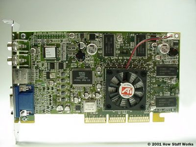
What is a graphics card and how does it work
Think of a graphics card as a specialized expansion board for your PC. Physically, it looks a lot like a motherboard. It is a printed circuit board packed with electronic components. At the center sits a dedicated processor, usually called a GPU, which handles all the visual calculations. Next to that processor, the board holds its own RAM, or video memory, to store image data temporarily.
This specific hardware setup matters for one main reason: speed. Your main CPU tries to handle everything, but rendering complex 3D environments, lighting effects, and high frame rates is a heavy load. The graphics card offloads that work. If you play computer games, this component determines whether your experience is smooth or stuttering.
Why gamers need a dedicated GPU
Why is this piece of hardware so critical for gaming? Because modern games rely on real-time rendering. Every frame on your screen is calculated in milliseconds. A weak graphics card struggles to keep up, leading to low frame rates or graphical glitches. A strong one handles the pixel data from its own video memory and sends it to your display before the next frame is even calculated.
The distinction here is between integrated and discrete graphics. Integrated graphics live on the motherboard or processor itself. They save space and power but share memory with the system. A dedicated graphics card is a standalone unit. It has its own processor, its own cooling system, and its own dedicated RAM. That separation is what allows for high-performance gaming.
How video memory affects performance
The RAM on a graphics card is not the same as your system RAM. It is specialized video memory. Think of it as a scratchpad for the GPU. The more detailed the game, the more data that needs to be accessed instantly. Textures, shadows, and particle effects all live in this memory. If you run out of space, the GPU has to reach out to your slower system RAM, which kills performance.
This is why specs like VRAM size matter. A game running at 4K resolution demands significantly more video memory than one running at 1080p. If you are looking at hardware for gaming, the amount of RAM on the card is a direct indicator of how much visual complexity it can handle without breaking a sweat.
Where the graphics card fits in your PC
Where does this card go? It plugs into a PCIe slot on the motherboard. This slot provides the high-bandwidth connection between the graphics card and the rest of the system. The card also needs power, usually from dedicated 6-pin or 8-pin cables coming directly from your power supply.
Once installed, the card takes over visual output. You connect your monitor to the ports on the back of the card, not the motherboard. This ensures the image is being processed by the dedicated GPU, not the integrated graphics on your CPU. It is a simple swap, but it changes how your entire system handles visuals.
The graphics card is essentially a mini-computer dedicated to one task: making pixels appear in the right place, in the right color, as fast as possible.
Which components make up a graphics card
Breaking down the board, you will find a few key elements. The GPU is the brain, executing the instructions that define what you see. The video RAM holds the data being processed.
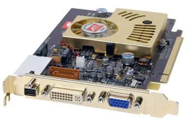

What kills PCIe?
PCI Express, or PCIe, did a lot of heavy lifting. It replaced the aging AGP standard by handling significantly more data throughput and delivering increased power to video cards. It became the backbone of modern desktop and laptop computing for over a decade.
But that picture? It’s not PCIe.
The item shown is the M.2 form factor, specifically in its NVMe SSD configuration. While M.2 can technically use PCIe electrical signaling, it is often confused with the physical PCIe slot on the motherboard. The real shift here is architectural. M.2 drives bypass the traditional SATA bottleneck entirely. They plug directly into the motherboard’s PCIe lanes.
This matters because latency drops.
| Feature | Legacy SATA SSD | M.2 NVMe (PCIe) |
|---|---|---|
| Interface | SATA III | PCIe 3.0/4.0/5.0 |
| Max Sequential Read | ~600 MB/s | 3,500 MB/s to 14,000+ MB/s |
| Power Consumption | Moderate | Low (direct board power) |
| Heat Profile | Lower | Higher (requires passive/active cooling) |
Why the change? Speed.
SATA was designed for hard drives in the 2000s. It caps out at 6 Gbps, which translates to roughly 600 MB/s. That was a massive leap from HDD speeds, but it’s a ceiling. PCIe Gen 3 x4 lanes push 3.5 GB/s. Gen 4 hits 7 GB/s. Gen 5 doubles that again.
For everyday users, this means:
1. Faster app loading. No waiting for heavy software like video editors or large games to initialize.
2. Quicker file transfers. Moving 50 GB of footage becomes a background task instead of a project.
3. Better system responsiveness. The OS can prefetch data more aggressively without I/O bottlenecks.
Is M.2 always better? Not necessarily.
If you’re buying a budget laptop with a SATA M.2 drive, you’re still stuck at 600 MB/s. The form factor is the same; the protocol is different. Check the specs. Look for “NVMe” or “PCIe x4” in the product description. If it says SATA, you’re getting the slow version.
Also, heat becomes a variable. NVMe drives generate more heat than SATA SSDs. Thin laptops often throttle performance under sustained load to protect components. A desktop with good airflow won’t notice. A compact all-in-one might.
The next step? PCIe 5.0.
It’s not just double the speed. It’s double the bandwidth. But it also doubles the power draw and heat. Manufacturers are currently balancing performance with thermal management. Consumer drives are hitting 12,000+ MB/s. Is that useful? For 8K video editing, yes. For browsing the web, no.
The real question isn’t about raw speed. It’s about whether your workflow demands it. If you’re moving massive datasets or rendering complex scenes, the PCIe interface is non-negotiable. For general use, a Gen 3 NVMe drive is more than sufficient
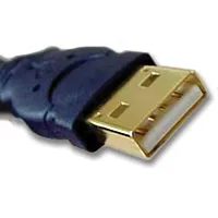
How USB connectivity shapes modern PC hardware
Universal Serial Bus ports are standard on almost every machine you can buy right now. They handle mice, keyboards, printers, and external drives. The design solves a problem that plagued earlier computing: confusing, non-standard connections.
USB lets you plug things in and out while the system is running. No restarts. No fumbling with different port types. The protocol handles power and data over the same cable.
Why does this matter for everyday users?
- Device compatibility – One cable type covers most peripherals.
- Hot-swapping – Connect or disconnect devices without powering down.
- Power delivery – Small devices like phones or wireless dongles draw electricity directly from the port.
The shift away from older connectors like PS/2 or proprietary printer cables simplified setup. You don’t need to match colors or shapes anymore.
Which USB versions actually exist on your PC
Not all ports are created equal. Speed and power output vary between generations.
USB 2.0 tops out at 480 Mbps. It’s fine for mice and basic storage. USB 3.0 jumps to 5 Gbps. USB 3.1 pushes 10 Gbps. USB 4 reaches 40 Gbps.
Each step up changes what you can do. Fast video editing or large file transfers benefit from the higher bandwidth tiers. But for typing or printing, USB 2.0 still works just fine.
Check the physical connector shape. Type-A is the flat, trapezoidal design most people recognize. Type-C is smaller, reversible, and now standard on newer laptops and phones. The port type tells you which cables will fit.
How USB affects daily workflow and device selection
When you buy a new mouse or webcam, you’re mostly choosing between USB-A and USB-C compatibility. Most adapters exist, but direct connections reduce friction.
The real impact shows up when you add peripherals. A single hub can expand one port into six. That lets you connect a printer, external drive, and phone charger from one slot.
Power delivery matters more than people realize. A high-draw device like a portable hard drive needs a powered hub or a data-only port with external power. A mouse needs almost nothing.
The standard also enabled the growth of thumb drives. Before USB, copying files required floppy disks or proprietary cables. Now a single pocket-sized stick holds terabytes.
Where USB falls short for demanding tasks
High-end video editing, 3D rendering, or large-scale data backups can outstrip even USB 4 speeds. Internal drives and Thunderbolt connections handle those heavier loads.
USB also limits the number of devices you can chain before performance drops. A deep hierarchy of hubs can introduce latency or power shortages.
For most home and office use, though, USB covers the needs. The convenience outweighs the ceiling.
You’ll notice the ports more when they fail. A dead USB port means a disconnected printer or a phone that won’t charge. The fix is usually simple: try another port, swap the cable, or reset the controller through Device Manager.
The standard won’t go away anytime soon. Newer versions keep pushing speed and power, but the basic idea stays. Plug it in, and it works.
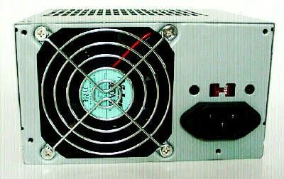

Line Voltage Switches on PC Power Supply Units
That small, red switch sitting just above the power cord connector on the back of your power supply unit (PSU) controls the line voltage setting. It exists because electrical standards vary by region. In North America, you deal with 120V AC. In much of Europe and Asia, the standard is 220V or 230V AC.
If you buy a PSU in the US and plug it into a European outlet without flipping that switch, you might damage the hardware. The switch tells the internal circuitry how much power it is receiving so it can regulate it down to the safe DC levels your components need.
Why Your PSU Has a Manual Voltage Selector
Modern PSUs often use automatic voltage detection, making that red switch obsolete. But many units still rely on the manual toggle. Here is why.
- Cost and design simplicity: A manual switch is cheaper to implement than the circuitry required for auto-sensing.
- Reliability: There is no software or sensor to fail. It is a physical connection.
- Legacy standards: Some older industrial or specialized server PSUs still prioritize the manual selector for strict compliance with specific regional standards.
How to Set the Line Voltage Correctly
Check the label on the PSU. It will likely have a small diagram near the switch showing two positions: 115V or 120V on one side, and 230V or 220V on the other.
- Unplug the unit. Never change this setting while the PSU is connected to a wall outlet.
- Match your local grid. If you are in the US, Canada, or Mexico, set it to 115V/120V. If you are in Europe, the UK, or most of Asia, set it to 220V/230V.
- Verify the position. The switch should click firmly into place.
What Happens If You Get It Wrong
The consequences depend on the direction of the error.
- Setting 115V switch to 220V wall: You are telling the PSU it is receiving 220V when it is only getting 120V. The PSU will likely not turn on. It will think the input voltage is too low to operate safely.
- Setting 220V switch to 115V wall: This is dangerous. The PSU expects 115V but gets 220V. The internal capacitors and transformers will handle double the intended stress. This can cause immediate failure, smoking, or fire.
Which PSUs Still Use This Switch?
You will find these most commonly in:
– Older consumer PSUs (pre-2010 models).
– Budget PSUs from generic manufacturers.
– Certain server and workstation PSUs designed for global deployment without automatic detection.
Brands like Corsair, Seasonic, and EVGA have largely moved away from manual switches in their consumer lines, opting for auto-switching designs. However, if you are building a budget rig or reusing older parts, you will encounter this red switch.
Is There a Way to Check Without Opening the Case?
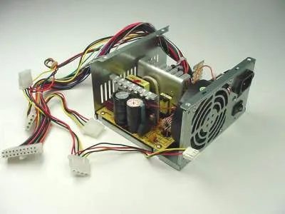
How switcher technology turns AC into usable DC
PC power supplies rely on switcher technology to handle the conversion process. The job is straightforward in theory. Take that alternating current from the wall and chop it down into steady, usable direct current. The hardware does this by rapidly switching transistors on and off.
You get specific outputs from this process. Digital circuits, like your CPU and memory, typically draw from the 3.3-volt and 5-volt lines. Those rails feed logic gates and memory chips. Meanwhile, the 12-volt line handles mechanical work. It spins the motors inside your disk drives. It keeps your case fans turning.
Why the distinction? Because electronics and mechanics have different power needs. Logic wants stable, low voltage. Motors need higher voltage to generate torque. The switcher handles both efficiently. No wasted heat. No bulky transformers generating waste heat. Just clean power distribution to the components that need it most.
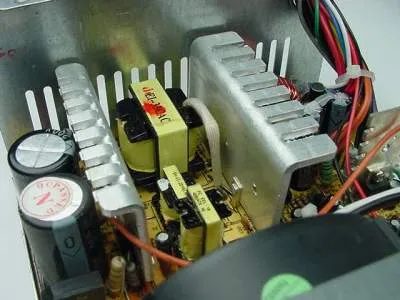
What are the yellow components in the center?
Those three small yellow blocks are transformers. They sit right in the middle of the layout. To their left, you’ll spot two cylindrical capacitors. The big, finned aluminum pieces scattered around? Those are heat sinks.
Why do power supplies use large aluminum heat sinks?
Heat sinks exist for one reason: to dump excess heat into the air. Semiconductors like transistors and diodes generate significant thermal energy during operation. If that heat stays trapped inside the component, it fails.
The fins increase surface area. More surface area means more contact with the surrounding air. That allows the heat to dissipate faster. Without them, the internal temperature would climb well beyond safe limits.
Take a closer look at a heat sink next.
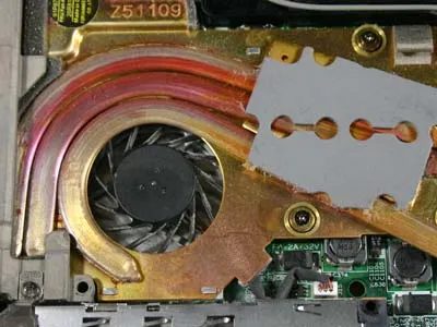
Laptop Cooling: The Hidden Hardware Working Like a Desktop
You see a heat sink and fan in a laptop, similar to the hardware in a desktop. That’s the core. But it’s tightly packed. No room for airflow. The metal heatsink grabs heat from the CPU, and the tiny fan pushes air out through slits. It works. Just like a desktop PC, but squeezed into a chassis.
The engineering challenge isn’t the components. It’s the space they occupy.
Desktops breathe. Laptops choke. That’s why your laptop gets hot on your lap. The fan spins up, then down, then up again. Thermal throttling happens if you push a modern laptop too hard. The CPU slows down to stay cool. You lose performance, but you save the hardware.
Why does it matter? Because you want speed without melting. Modern chips run hot. The cooling solution is the bottleneck. A better fan doesn’t just lower noise. It buys you sustained performance. Check your laptop’s thermal design power (TDP). It tells you how much heat the cooling system can handle. If you’re editing 4K video, you need a robust setup. A basic office laptop won’t cut it.
How do you know if your cooling is struggling? Listen. Feel. Check task manager for CPU speeds dropping under load. If the clock speed dips below the max while usage sits at 100%, the thermal limit is hit. That’s not a software bug. It’s physics.
Which laptops handle heat best? Look for vapor chambers. They spread heat across a larger area before the fan moves it. Some premium ultrabooks use this tech. Others stick to simple heat pipes. The difference in sustained performance can be 15-20%. That’s not negligible.
The desktop comparison holds up, but with caveats. A desktop tower has volume. A laptop has constraints. You trade space for portability. You accept higher temperatures, louder fans, and potential throttling. It’s the price of carrying your workstation in a bag.
Does it affect everyday users? Absolutely. If your laptop slows down after 20 minutes of video calls, check the vents. Dust clogs them. The fan works harder. Efficiency drops. A $10 can of compressed air fixes that. Or a proper cleaning. Don’t ignore it.
The heat sink and fan aren’t just parts. They’re the enablers. Without them, modern CPUs die in seconds. The tech is invisible until it fails. Then it’s the first thing you notice.
Stay cool. Literally.


